Valve Seat Repair or Maintenance - Grinding of a Gate Valve Seat
The below instructions are for use with the Model G Valve Grinding Tool
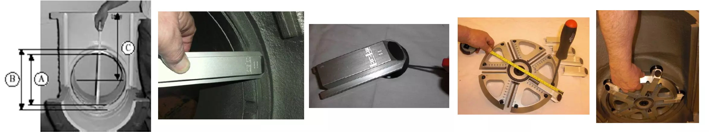
To prepare for the grinding process, it is important to determine the internal diameter (A) and external diameter (B) of the seat and evaluate the angle, if necessary. Accurate measurement of the distance (C) between the center of the seat and the top of the flange is also crucial.
Before proceeding with the grinding process, it is essential to clean the valve to remove any moisture and dirt that could potentially interfere with the performance of the machine and grinding material.
In case your G-machine is equipped with a pneumatic drive unit, it is important to verify that you have a sufficient air supply with a maximum pressure of 8bar.
To ensure efficient and effective grinding, it is recommended to choose the appropriate driving head and grinding arms based on the measurement of A and B. It is also crucial to confirm that there is adequate space for the grinding head with arms to move freely, specifically checking the clearance between the seat and the valve guide.
In instances where the seat width is greater than 25mm, it is recommended to use 50mm adaptor plates for the grinding heads. For seat widths wider than 45mm, it is recommended to use 70mm adaptor plates. In other cases, use the largest adaptor plates available.
The grinding head and arms are marked for proper assembly. The number on the head is located next to the slot where the arm should be mounted, and the number on the arm is marked on the front top. It is crucial to match the arm and slot numbers (e.g. 1 on 1, 2 on 2, etc.) during assembly.
After assembling the grinding arms on the driving head, it is important to check that there is adequate space in the valve for the driving head to move freely.
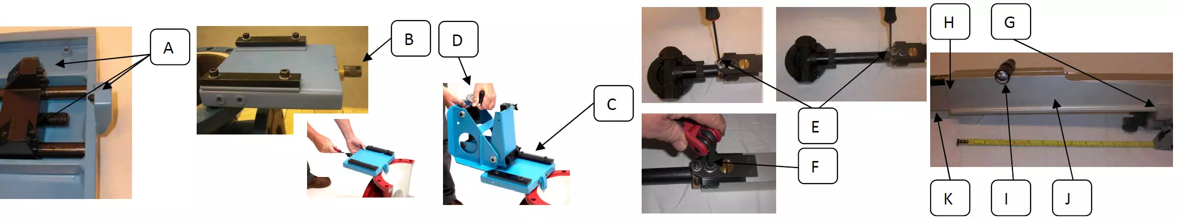
To assemble the mounting plate, start by ensuring that the pointed grub screws on the clamp (A) are visible 6-8 mm. Then, fasten the mounting plate on the flange or valve body and secure it by tightening the clamp screw (B) with a torque of about 20 Nm. The ideal location for the mounting plate is behind the seat for ease of grinding, but it can be placed anywhere around the flange if necessary. Confirm that all three pointed grub screws (A) are locked onto the body. If the flange has non-removable bolts, it is recommended to use the mounting device for narrow seats (part number 90 401 00).
To assemble the machine frame, position the drive shaft clamp so that it extends over the seat to create a positive angle between the drive shaft and the seat. Tighten the four screws (C) and adjust the drive shaft mount plate so that it is perpendicular to the pressure feed (D). Loosen the screw on the brass bushing (E), pull out the shaft to its outer position, and tighten the screw (E) again. Finally, tighten the screw (F) to allow the round shaft with the brass bushing to turn freely.
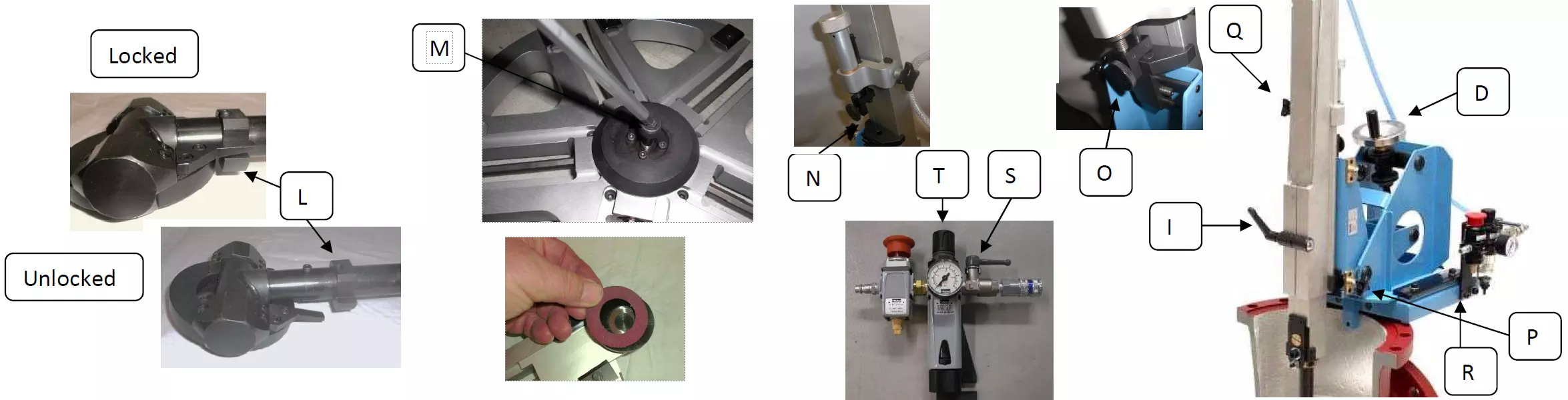
To adjust the height of the holder, move the height adjustment clamp (G) to a location about 20cm (8 inches) from the front edge (H) of the holder. Then, release the handle (I) on the holder (J) to make the driveshaft (K) movable. Pull the driveshaft into the correct position by using the measurement between the center of the seat and the top of the flange. Ensure that the distance between the front edge (H) of the holder and the center screw is the same. When in position, lock the handle (I) on the holder. Finally, confirm that the tilt lock (L) is in the locked position.
Place the driving head onto the drive shaft, making sure that the gears mesh properly to prevent stripping. Slowly turn the head to feel for any skipping in the gears. Once the gears are properly engaged, lock the driving head by tightening the center screw (M) with a torque of about 20Nm.
Next, select and add the grinding discs of your choice. The use of LarsLap Grinding Discs SPY/SPX in conjunction with the LarsLap valve grinders has proven to be highly effective in achieving optimal results. The grinding material, a blend of Aluminium Oxide and Ceramic, is capable of handling even the hardest materials and can remove a significant amount of material with ease. The use of diamond discs and LarsLap Long Life boron nitride discs are recommended for removing even harder seat materials. In addition to heavy cutting, the Grinding Discs are also ideal for finer types of grinding and polishing. The use of LarsLap 3M discs ensures that the grinding grains are of uniform size, resulting in a smooth surface on most materials. With the ability to grind down to 3 microns, the grinding options are vast. For hard surfaces, diamond is the recommended option, however, it should not be used on materials such as brass and stainless steel. In such cases, the use of LarsLap Long Life boron nitride is recommended for stainless steel. While water can be used as a lubricant, it is important to note that excessive speed may cause the diamond to burn. For lapping surfaces, diamond paste or diamond slurry is the preferred option for polishing purposes. These products are specifically designed to provide a smooth and polished finish on lapped surfaces.
Next, hold the drive unit steady and mount it onto the machine frame by carefully sliding it into position. Ensure that the fixed point depth adjustment clamp ball (N) falls into place and lock it by tightening the knob (O). Secure the holder with the clamp knob (P) and set its position by tightening the adjustment clamp. To make adjustments in the horizontal plane, use the side adjustment knob (Q). For vertical adjustments, hold the drive shaft using the hose (in the case of pneumatic) or the drive unit (in the case of electrical), loosen the drive shaft tightening handle on the holder (I), adjust the depth to the desired position, and then tighten it again. Note that it is important to use care while adjusting the drive shaft depth, as a dropped drive shaft could cause damage to the equipment. Finally, adjust the drive shaft angle by using the grinding pressure knob (D).
Pneumatic Option: To attach the speed regulator on the mounting plate, use the two screws (R). Once attached, connect the air hose between the drive motor and the speed regulator, and then connect the air hose between the drive motor and the silencer. Before connecting the air supply, make sure that the shut off valve (S) is closed and the air regulator (T) is turned counterclockwise and closed. To operate the knob, lift the knob and then turn it. Once the valve is open, use the air regulator to control the speed.
Begin by adding a light grinding pressure and rotating the driving head by hand one turn to ensure there is enough space around the seat. To activate the machine, lift the emergency stop button and open the shut off valve (S) to its maximum, then turn the regulator knob (T) clockwise until the correct speed (60-80 rpm) is reached. Adjust the grinding pressure to half to a full revelation on the grinding pressure knob.
It is recommended to change the direction of rotation every 5-10 minutes to optimize the performance of the grinding discs. It may be necessary to adjust the air input when operating the air motor in the reverse direction due to power loss.
When changing grinding discs, stop the machine by turning off the shut off valve (S) and disconnecting the air hose. Release the grinding pressure and loosen the holder with the clamp knob (P) and the fixed point depth adjustment clamp ball knob (O). Carefully lift the entire drive unit out of the valve and replace the grinding discs. After the discs are switched, re-install the drive unit, tighten the clamp knob (P) and the fixed point depth adjustment clamp ball knob (O), reconnect the air supply, and add grinding pressure to continue the grinding process.
To grind the seat on the opposite side, rotate the drive shaft 180° and add pressure in the opposite direction
Upon completion of the grinding process, thoroughly inspect the machine for any signs of damage. Ensure that all components have been properly cleaned and dried before reassembling and returning them to their storage case. Conduct a final check to confirm that all parts are accounted for and securely stored.