Microstructure and Materials Analysis
In order to subject a material to structural analysis, it must be prepared according to the requirements of metallography. Only after an error-free preparation can a microscope be used to look into the interior structure. For this, the cutting, mounting, grinding and polishing of the sample is essential.
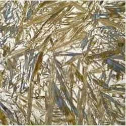
Microstructure analysis of steel structures
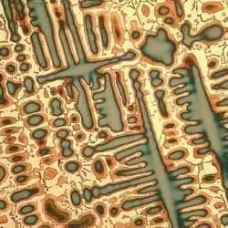
Microstructure Analysis Copper Alloy

Microstructure Analysis Zinc
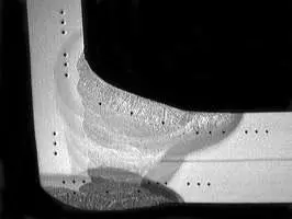
Microstructure Analysis - Preparation: Weld - Hardness Test
In a weld process test, the sample is also processed metallographically. In the zones hardness tests are carried out at a defined position to determine an increase in hardness (embrittlement). An acid etch makes the different zones visible:
- Base material (material to be connected)
- Heat-affected zone (base material modified by the effect of heat)
- Melting material (welding additive, flux, welding wire)
In addition, welds / their zones are documented macroscopically and measured.
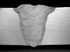
Hardness test impressions in a butt joint V weld
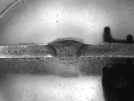
Hardness test impressions in an embedded butt weld
Hardness test impressions in a corner joint weld
Microstructure Analysis - Preparation: Hardness Test
Vickers / Knoop / Brinell
In addition to microstructural analysis, the metallographic preparation is used for the preparation of a hardness test (typical for Vickers) on the sample surface or for hardness profiles. A polished surface is generally required because todays software used in automatic hardness test machines cannot accurately determine the indenter impression if it is surrounded by scratches. This applies in particular to an automated hardness test by means of a fully automatic machine for the following evaluations:
- CHD (EHT) Case Hardness Depth
Subsequently, hardness indents are applied at precisely defined distances; see illustration below. The test method to be used can be both Vickers and Knoop with a test force between 0.98 - 9.8 N. The Case Hardness Depth (Chd) is derived from the curve representing the hardness in dependance of the distance from the edge of the specimen surface (edge distance) by measuring the edge distance up to a limit hardness of 550 HV or the corresponding Knoop hardness value.
- SHD (RHT) Surface Hardness Depth
The hardness indents are arranged on one or more lines perpendicular to the specimen surface, with a width defined in the standard. The test force to be used is 9.807 N (HV). The surface hardness penetration depth is derived from the curve representing the hardness over distance from the surface by measuring the distance from the surface to the calculated limit hardness (GH).
- NHD (NHT) Nitriding Hardness Depth
This is ascertained from a minimum of three hardness test indents and allows the hardness limit to be obtained. Subsequently, hardness indents are applied from the edge to the workpiece interior at precisely defined distances. The test method to be used is Vickers in the low-load range. The nitriding hardness depth is derived from the curve representing the hardness over distance from the surface by measuring the distance from the surface to the calculated hardness limit.
- CD (At) carburizing depth
- CLT (VS) bonding layer thickness
- Hardness courses on components


CHD (EHT) case hardening depth

SHD (RHT) surface hardening depth

NHD (NHT) nitriding hardening depth
Separation for Microstructure Analysis - Investigations: To enable a view into the interior
In order to obtain a sample usable for metallography from a material or component, the material has to be cut in the first step. Since the effect of heat would distort the material characteristics (microstructure and hardness), thermal processing methods (burning or plasma particles) are fundamentally ruled out. Machining processes are also considered to be unsuitable: A saw cut produces a rough edge that has to be ground down in a complex process / milling produces a material compaction (work hardening). The standard way of cutting specimens for analysis is to use a cut off machine with an abrasive blade matched to the material in hardness. These cut off wheels are designed to break down, continuously revealing fresh cutting edges, to maintain the best cutting action generating the least amount of heat. 99% of applications will use wet cutting to help keep the sample cool.
Once a sample has been cut, the next step is generally to mount the cut section to make it easier to grind and polish. There are 2 methods of mounting; hot mounting which uses a hot mounting press to produce a controlled sample puck from 25mm-50mmø, or cold mounting which uses re-usable moulds and epoxy or acrylic resins. An ECOPRESS hot mounting system will produce a mounted sample every 10-15 minutes. For high volumes of samples it is better to prepare them in cold mounting resins. Multiple reusable moulds can be filled manually with liquid resins and then left for 10 minutes to 24 hours, depending on the type of resin ready for processing when cured. There are many different types of hot and cold mounting resins and powders, some with particular edge retention, some are conductive for SEM analysis, some are perfectly clear and some are coloured.
Grinding and Polishing: Microstructure Analysis - Cuts for exact evaluations
Once cut, viewing the section under a microscope or hardness tester lens, the specimen surfaces will appear rough and uneven. In order to evaluate the true properties, they must be ground and polished. It is only in the high-gloss polished state that a qualified statement can be made about grain sizes, grain boundaries, microstructural fractions, inclusions, Vickers hardness, weld seam zones etc. Kemet do offer grinding and polishing machines for this task, with different configuration levels for manual preparation and automated preparation by means of single pressure or central pressure system: With the basic unit of the Forcipol grinding and polishing machine series, material samples can be ground manually.
For higher sample volumes or higher demands on the quality of the cut (flatness / edge sharpness), the Forcimat 52 is recommended. This low-priced solution increases the efficiency of sample preparation many times over and ensures reproducible samples even for a beginner in metallography. This task can be fulfilled even more efficiently with the programmable Forcimat 102. With storage for 30 different programs to prepare a wide variety of samples (steel, aluminum, titanium) this makes a significant contribution to the efficient utilisation of staff. This machine can offer high throughput and error-free preparation working on different materials with different (stored) preparation methods. If a high material removal is required for the test specimens (welding seams, large volume samples), the Forci Plan surface grinding machine can offer decisive advantages: High removal volume in shortest time, perfect flatness between sample surface and underside (important for hardness courses), direct re-clamping of the sample holder from this grinding machine back to a Forcimat head maintains the flatness and parallelism in a quick and easy way.


